Support
Technical Information
Assortimento Raccordi a Rame
General Specification
This general specification provides an overview of the key features and capabilities of the product range. However, it is important to review the specific technical details and credentials of each individual product before use, as these may vary. Always verify that the product meets your specific requirements and standards for your intended application.
Products
This technical data sheet outlines the general specifications for the products listed below. Please be aware that specific details may vary between products. For precise information tailored to each product, please consult the relevant product page on our website.
Product Codes
4090G, 4092G, 4130G, 4243G, 4270G, 4341G, 5001a, 5002a, 5040, 5041, 5085, 5086, 5090, 5092, 5130, 5130R, 5240, 5243, 5270, 5301, B020, C803SFEF, C805SCEF, C901EF, C903SFEF, C904LEF, C905SCEF, C906EF, FA, FFL5221, P440EF, P717EF, P737EF, P803WPEF
Approvals
Flowflex holds ISO certifications independently audited by the British Standards Institute, ensuring credibility and trust with consumers, clients, and business partners alike. We take pride in these certifications and are committed to continuous improvement to better serve our clients.

Standards
The products in this range are manufactured in accordance with the following standards to ensure superior quality, safety, performance, and compatibility:
Standards
The products in this range are manufactured in accordance with the following standards to ensure superior quality, safety, performance, and compatibility:
- BS EN 1092-3: Connections with Copper Alloy Flanges
- BS EN 1254: Copper and Copper Alloy Plumbing Fittings
- BS EN 1254-1: Capillary Fittings for Soldering or Brazing to Copper Tubes
- BS EN 1254-5: Capillary Fittings With Short Ends For Brazing to Copper Tubes
Connections
The products in this range are engineered to establish connections in compliance with the following standards:
- BS EN 1092-3: Connections with Copper Alloy Flanges
- BS EN 1254-1: Capillary Fittings for Soldering or Brazing to Copper Tubes
- BS EN 1254-4: Plumbing Fittings with Threaded Connections
- BS EN 1254-5: Capillary Fittings With Short Ends For Brazing to Copper Tubes
- BS EN ISO 17672: Brazing Alloys
- BS EN ISO 9453: Soft Solder Alloys
- ISO 228-1: Parallel Threads
- ISO 7-1: Tapered Threads
Complimentary Products
The products in this range are specifically designed to work with products that adhere to the following standards:
- BS EN 1057: Copper Tube for Water and Gas in Sanitary and Heating Applications
- ISO 228-1: Parallel Threads
- ISO 7-1: Tapered Threads
Working Conditions
All working conditions assume that the components have been assembled and connected correctly, and adhere to their respective tube compatibility.
If you are planning to use our products in applications outside the scope of our recommendations, approval must be sought from us beforehand. Please contact us in these cases.
Plumbing Fittings with Threaded Connections
Applicable Products
4090G, 4092G, 4130G, 4243G, 4270G, 4341G, B020, C803SFEF, C805SCEF, C903SFEF, C905SCEF, FA, P717EF, P737EF, P803WPEF
Working Conditions for use with Liquidi
| Temperature (°C) | Pressure (bar) |
|---|---|
| 1/8" to 4" to ISO-228 | |
| 10 | 16 |
| 30 | 16 |
| 95 | 6 |
| 2 1/2" to 4" to ISO-7 | |
| 10 | 10 |
| 110 | 10 |
| 110 | 0 |
| 1/8" to 2" to ISO-7 | |
| 10 | 16 |
| 110 | 16 |
| 110 | 0 |
Working Conditions for use with Aria Compressa
| Temperature (°C) | Pressure (bar) |
|---|---|
| 1/8" to 4" to ISO 228 | |
| 5 | 6 |
| 35 | 6 |
| 35 | 0 |
| 1/8" to 4" to ISO-7 | |
| 5 | 10 |
| 35 | 10 |
| 35 | 0 |
Working Conditions for use with Gas Combustibile (MOP 1)
| Temperature (°C) | Pressure (bar) |
|---|---|
| 1/8" to 2" | |
| -20 | 1 |
| 70 | 1 |
| 70 | 0 |
Working Conditions for use with Gas Combustibile (MOP 5)
| Temperature (°C) | Pressure (bar) |
|---|---|
| 1/8" to 2" | |
| -20 | 5 |
| 70 | 5 |
| 70 | 0 |
Connections with Copper Alloy Flanges
Applicable Products
FFL5221
| Temperature (°C) | Pressure (bar) |
|---|---|
| PN16 | |
| -10 | 16 |
| 180 | 16 |
| 200 | 13.5 |
| 220 | 11.3 |
| 250 | 8 |
| 260 | 7 |
Capillary Fittings With Short Ends For Brazing to Copper Tubes
Applicable Products
5041, 5090, 5130, 5130R, 5243, 5270, 5301
Working Conditions for use with Brasatura
| Temperature (°C) | Pressure (bar) |
|---|---|
| 108mm ≤ 159mm | |
| 30 | 5 |
| 65 | 3 |
| 110 | 2 |
Capillary Fittings for Soldering or Brazing to Copper Tubes
Soldering materials must comply with EN ISO 9453
Brazing materials must comply with EN ISO 17672
Use With Potable Water installations
When using soldering or brazing alloys that contain lead or cadmium, you should check your local regulations as in some cases it may not be permitted for potable water installations.
Applicable Products
5001a, 5002a, 5040, 5041, 5085, 5086, 5090, 5092, 5130, 5130R, 5240, 5243, 5270, 5301, C901EF, C904LEF, C906EF
Working Conditions for use with Saldatura a Piombo > 50%
| Temperature (°C) | Pressure (bar) |
|---|---|
| 6mm ≤ 54mm | |
| 30 | 16 |
| 65 | 10 |
| 110 | 6 |
| 54mm ≤ 108mm | |
| 30 | 10 |
| 65 | 6 |
| 110 | 4 |
Working Conditions for use with Saldatura a Stagno > 95%
| Temperature (°C) | Pressure (bar) |
|---|---|
| 6mm ≤ 34mm | |
| 30 | 25 |
| 65 | 25 |
| 110 | 16 |
| 34mm ≤ 54mm | |
| 30 | 25 |
| 65 | 16 |
| 110 | 10 |
| 54mm ≤ 108mm | |
| 30 | 16 |
| 65 | 16 |
| 110 | 10 |
Working Conditions for use with Brasatura
| Temperature (°C) | Pressure (bar) |
|---|---|
| 6mm ≤ 34mm | |
| 30 | 25 |
| 65 | 25 |
| 110 | 16 |
| 34mm ≤ 54mm | |
| 30 | 25 |
| 65 | 16 |
| 110 | 10 |
| 54mm ≤ 108mm | |
| 30 | 16 |
| 65 | 16 |
| 110 | 10 |
Applications
Products in this range are designed and manufactured to deliver reliable performance in the following applications. However, please review each product individually for detailed information on its specific intended uses.
- Gas Domestico a Bassa Pressione secondo EN 1775
- Aria Compressa
- Sistemi di Acqua Refrigerata
- Servizi di Protezione Antincendio secondo EN 12845
- Servizi di Acqua Calda e Fredda secondo EN 806
- Gas ad Alta Pressione secondo EN 15001
- Refrigerazione
- Sistemi di Riscaldamento Chiuso secondo EN 12828
- Sistemi di Drenaggio
- Combustibili Liquidi secondo 12514
If you plan to use our products outside of the specified applications, you are required to obtain our approval before proceeding with installation.
Preparazione
Choosing Your Brazing Alloy
When brazing Flowflex products, ensure that your brazing material adheres to the EN ISO 17672 standard.
If you have chosen an alloy that contains lead or cadmium, ensure that you are in compliance with your local regulations as in some cases it may not be permitted for potable water installations.
Choosing Your Soldering Alloy
When soldering Flowflex products, ensure that your soldering material complies with the EN ISO 9453 standard.
If you have chosen an alloy that contains lead or cadmium, ensure that you are in compliance with your local regulations as in some cases it may not be permitted for potable water installations.
Assemblaggio
Come Preparare il Tuo Tubo di Rame
Equipment
Tools
- Tagliatubi
- Utensile per Sbavare
- Protezione per le Mani
Supplies
- Tubo in Rame
Installation Steps
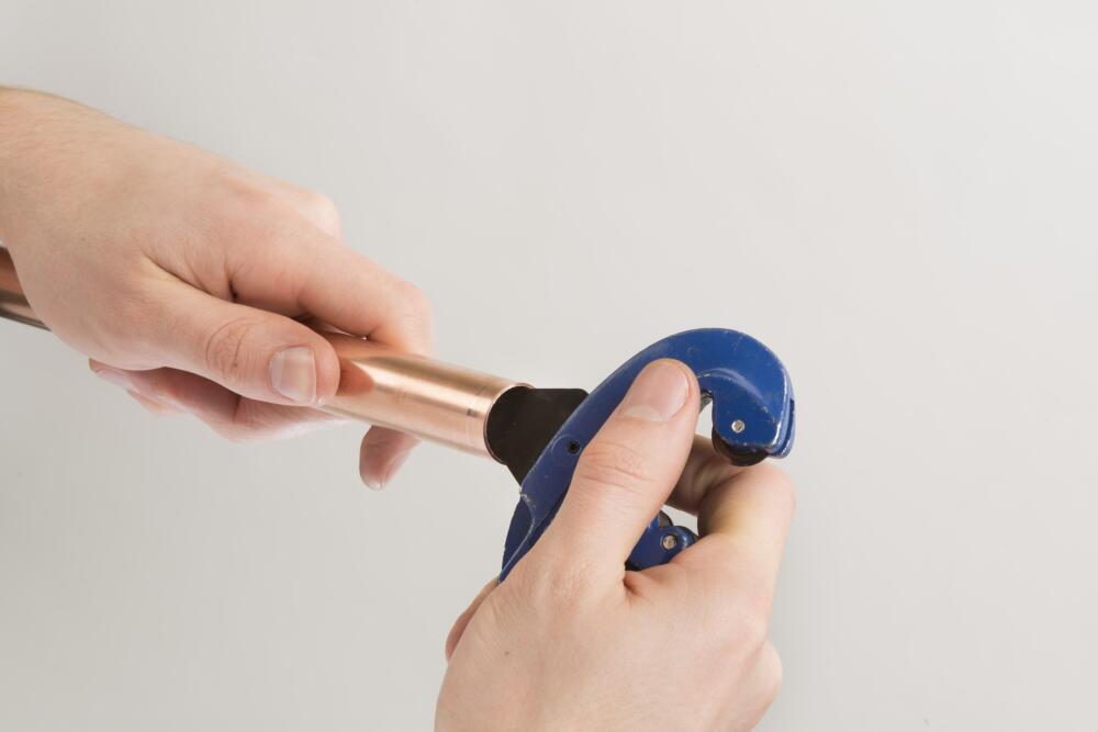
Taglia il Tuo Tubo alla Lunghezza Desiderata
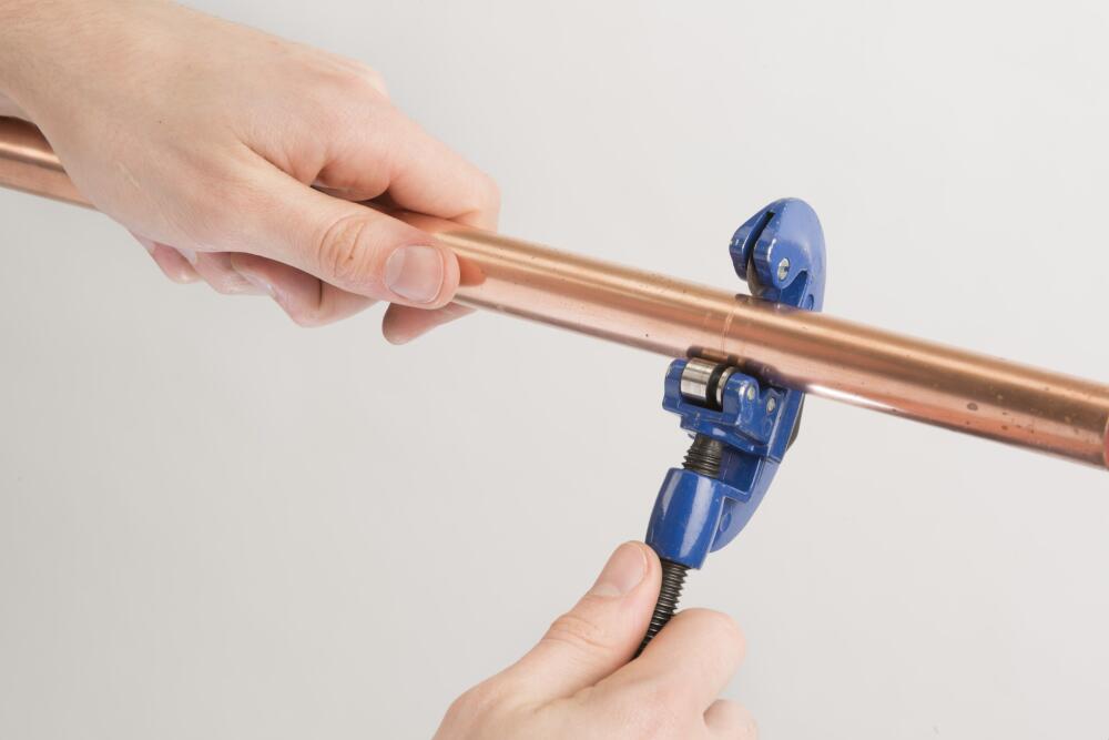
Taglia il tubo in modo netto lungo il diametro utilizzando un tagliatubi di qualità o un tagliatubi rotativo.
Taglia il Tuo Tubo con Precisione
È importante assicurarsi che le estremità del tubo siano pulite e tagliate ad angolo retto. Non farlo potrebbe influire sulla qualità della giunzione. Se il taglio non è piatto o il tubo è troppo corto, potrebbe non raggiungere lo stop del tubo compromettendo l'integrità della giunzione. Se è troppo lungo, potresti introdurre tensioni nell'intero sistema.
Pulisci la Presa del Tubo
Utilizzando il tuo utensile per sbavare, assicurati che l'interno del tubo sia liscio e non interferisca con il flusso.
Pulisci l'Esterno del Tubo
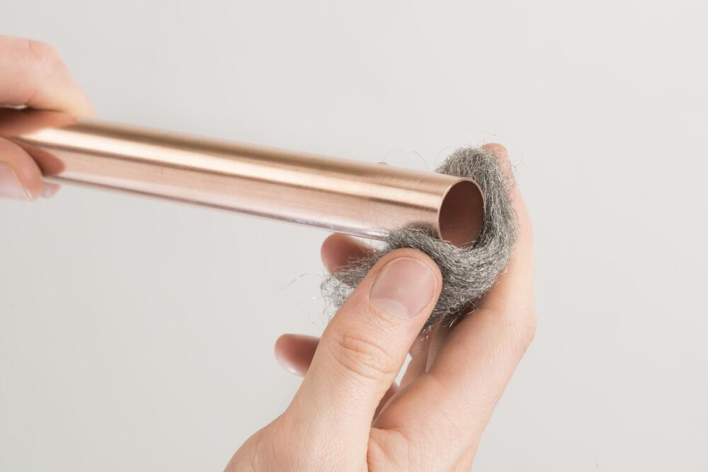
Pulisci l'esterno del tubo, assicurandoti che non ci siano residui di tubo, sporco o granelli vicino alla giunzione. Non rimuovere tutti gli ossidi o qualsiasi materiale nelle zone di sovrapposizione di raccordi e tubo può interferire con l'azione capillare, riducendo la forza della giunzione saldata, portando a un guasto.
Allo stesso modo, una pulizia eccessiva può rimuovere troppo materiale, provocando una vestibilità allentata e un guasto.
How To Install Flowflex End Feed Fittings
Equipment
Tools
- Flame
- Hand & Eye Protection
Supplies
- Copper Pipe
- End Feed Fittings
- Solder (EN ISO 9453) or Brazing Rod (EN ISO 17672)
- Flux
Installation Steps
Apply Flux
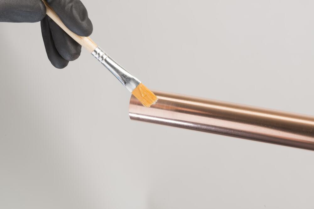
As soon as possible after cleaning, flux should be applied sparingly to the inside of the fitting and also the outside of the pipe at the point of overlap. This will help the capillary action and induce a stronger joint.
Assemble
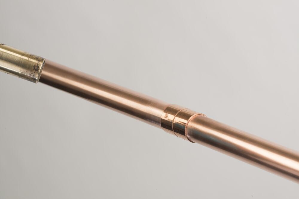
Insert the tube into the fitting until the pipe reaches the base of the pipe stop. A small twist can also be applied to ensure even coverage of the flux. At this point, excess flux should be wiped away using a rag.
Before proceeding to the next step, a uniform space around the circumference of the joint should be sought to allow for good capillary action. Excessive space can lead to cracking of the solder.
Heating
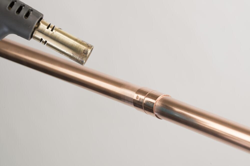
When heating, the entire circumference of the fitting should be heated evenly. It is recommended that you preheat the pipe and the fitting before applying direct heat.
Do Not Overheat the Joint
Do not overheat the joint or direct the flame into the face of the fitting cup. Overheating could burn the flux, which will compromise its effectiveness and the solder will not enter the joint properly.
Apply Solder
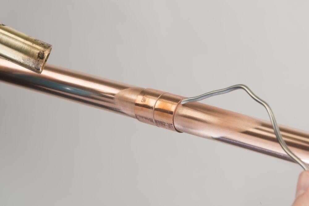
Touch the joint with the solder. If the solder does not melt, take it away and continue heating. If the solder begins to melt, push the solder into the joint whilst continuing to heat the base of the joint.
Solder joints depend on capillary action to draw the free-flowing solder into the narrow clearance between the tube and the fitting. Molten solder metal is drawn into the joint due to the capillary action, regardless of whether the flow is upwards, downwards or horizontal.
Cooling And Cleaning
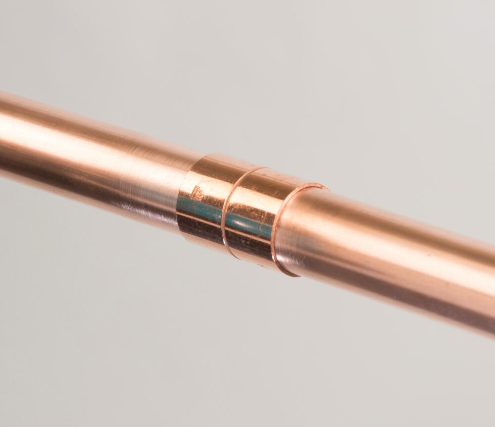
You should allow the joint to cool naturally. Cooling the joint forcefully could stress the joint.
When cool, remove any excess flux and residue with a wet rag.
Larger fittings require brazing instead of soldering. Brazing requires the same steps as above, but Brazing Rod must be used instead of Solder. Typically the Fitting will need to be heating to a much higher temperature also.
How To Assemble Threaded Connections
Threaded connections are typically either taper male threads to ISO 7 or parallel female threads to ISO 228. The most common sizes feature parallel male threads to ISO 228. These fittings are commonly used to connect pipework to boilers, pumps, and backplate elbows, ensuring secure and reliable connections in plumbing and heating systems.
By following these guidelines, you can ensure secure, reliable connections in your plumbing systems, enhancing overall performance and longevity.
Taper Male Threads
For taper male threads, apply a small amount of inert jointing compound or PTFE tape before installation. This ensures a secure and leak-free connection.
Parallel Male Threads
When installing parallel male threads, such as those used for cisterns and cylinders, a high-quality jointing washer should be used to create a reliable seal and prevent leaks.
Tightening Guidance For Threaded Connections
Size | Torque (Nm) |
|---|---|
1/2" | 75 |
3/4" | 100 |
1" | 125 |
1 1/4" | 160 |
1 1/2" | 200 |
2" | 250 |
2 1/2" | 300 |
3" | 370 |
4" | 465 |
Messa in Servizio
Testing Your Installation
Flowflex products are designed to comply with normal installation specifications, such as BS 806-4. As such, we strongly recommend that all systems are thoroughly tested upon completion. Whenever possible, completed systems should also be flushed to remove any debris, ensuring optimal performance and longevity.
Testing Hydraulic Installations
For hydraulic-based installations, the system should be tested to 1.65 times the system’s maximum operating pressure. This pressure should be maintained for at least 30 minutes to help identify any potential issues and confirms the system’s integrity.
If higher test pressures are required for your specific application, please contact us for further guidance and support.
Read Now
Testing Plumbing Installations
Considerazioni
Flowflex End Feed Electrical Continuity
Equipotential Bonding forms an important part of an installation, which ensures that all metalwork may be earthed or at least has the same potential to reduce the risk of equipment damage and personal injury. Isolated fittings or valves are not required to be bonded.
Flowflex End Feed Fittings provide guaranteed electrical continuity when correctly assembled with BS EN 1057 Copper Tube.
After all plumbing work has been completed, always ensure continuity checks are conducted by a qualified electrician in accordance with regulations (BS 7671).
Read Now
Electrical Continuity in Plumbing
Qualche Domande?
Il nostro team è pronto per te sempre.