Installation Instructions
Ball Valves Product Range

Last Updated

July 15, 2022

Flowflex reserve the right to alter the product ranges and specifications associated with its products without prior notice

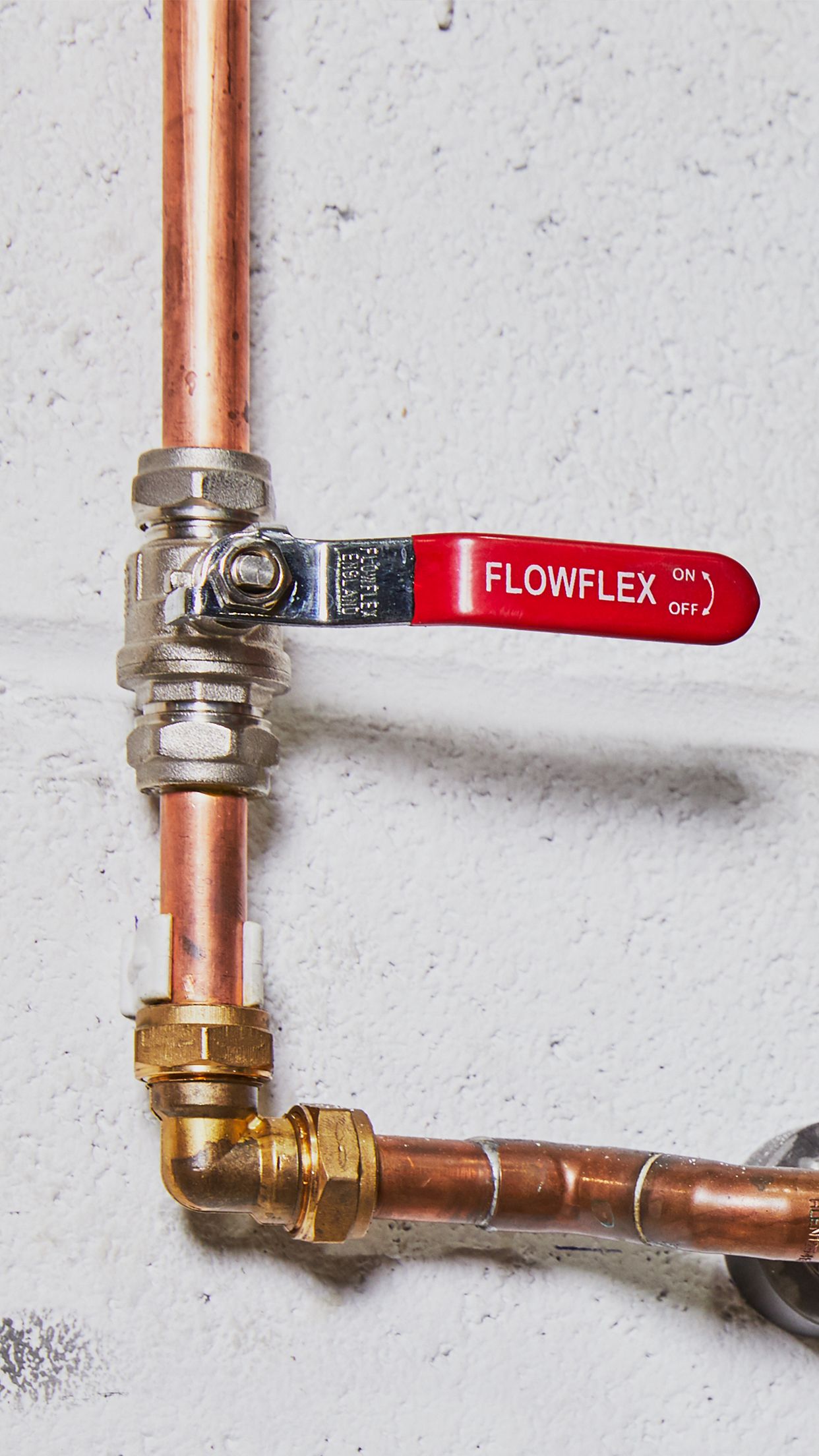
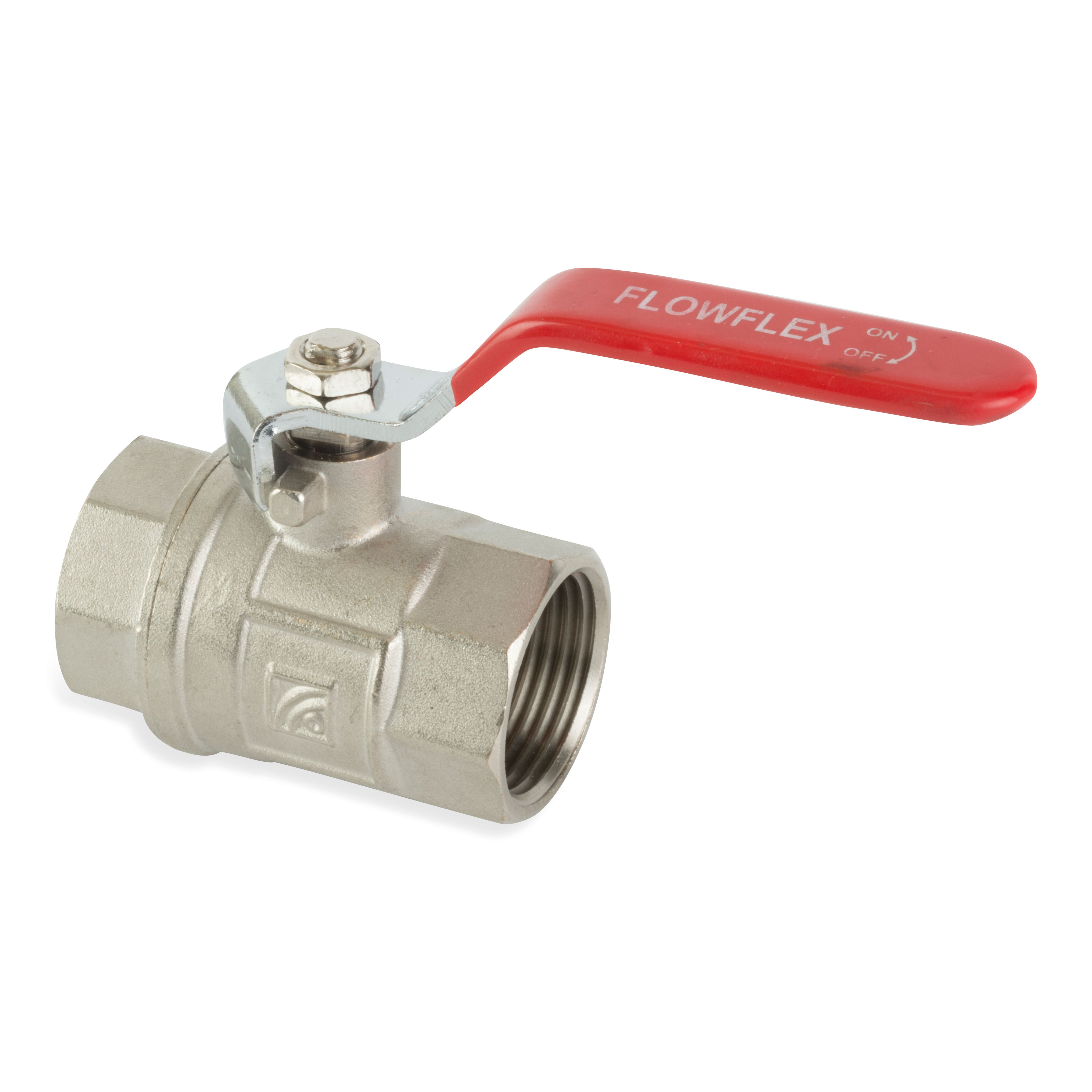
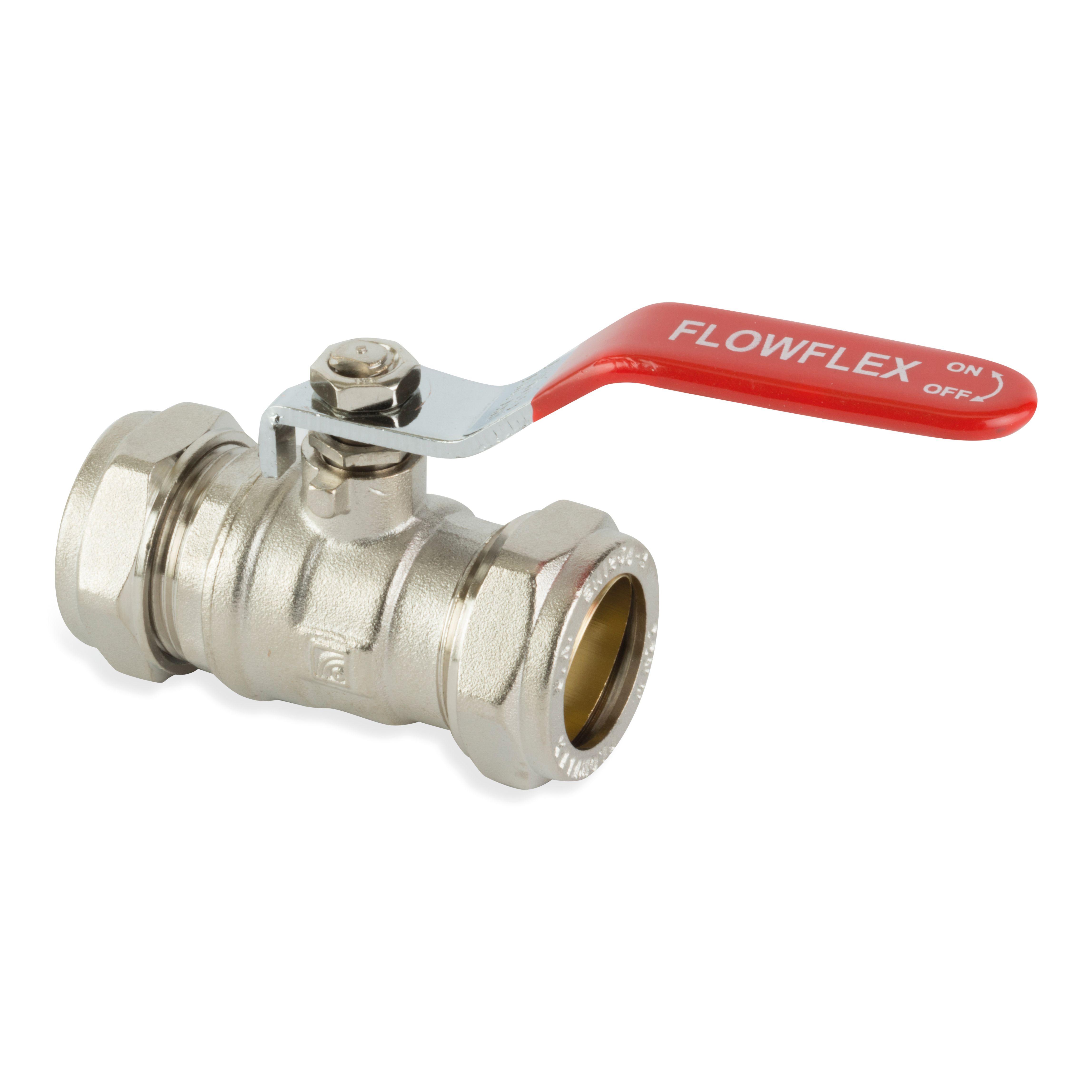
Flowflex Ball Valves are a quick way of isolating flow in a system. Flow is controlled through a quarter turn action which moves the hole in the ball inline or out of line with the flow, preventing or facilitating flow as appropriate.

Brass Ball Valves are regarded as a long term and reliable solution, performing well after long periods of disuse. The quick operation of a Ball Valve, is an advantage, and makes it ideal for emergency applications, however by the same merit, a disadvantage may be that Ball Valves induce water hammer in a system.

Applications

  • Domestic
  • Commercial
  • Industrial

Preliminaries

Unpack and check that the valve is correct for its intended usage. The valve must be compatible with the system design, pressure & temperature requirements and must also be suitable for the fluids it is intended to carry. Check that the flow paths are clear and that the threads are free from debris. To ensure ease of operation, maintenance and repair, the location of the valve should be decided during the system design phase. Valves should be appropriately supported to prevent strain on the valve and the pipework.

Equipment

Materials
  • Copper Pipe
  • Ball Valve
Tools
  • Adjustable Spanner
  • Pipe Cutting Tool
  • Internal & External Pipe Deburring Tool

Installation

Check Valve and Tube

Check Valve and Tube

Ball valves can be installed at any angle or orientation as long as there is enough space for 90 degree operation of the lever. Valves perform best when they are installed in an upright position.

Install with the valve in an open position

Ball Valves with Threaded Connections

Ball Valves with Threaded Connections

Ensure that the fitting is the correct size for the pipe. Fix the threaded pipe into a vice and apply compound to the male pipe threaded. Screw the valve onto the pipe and use spanner flats adjacent to the pipe joint being made. Use suitable supports to both ends of the valve in order to remove any stresses.

Do not over pack the threads, PTFE Tape is preferred.

Ball Valves with Compression Ends

Ball Valves with Compression Ends

Ensure that the fitting is the correct size for the pipe and that the pipe is cut to length with the ends square and clear from defects. Unscrew the nut and olive and slide onto the pipe. Insert the pipe into the fitting as far as the pipe stop. Slide the olive and nut back onto the fitting and tighten by hand until the pipe cannot rotate. Use spanner flats adjacent to the pipe joint being made.

Avoid over tightening.

Other Considerations

Tightening Guidance for Ball Valves with Compression Ends
Turns
Size Turns
< 28mm 1 1/4 Turns
> 28mm 3/4 Turns
Torque Settings
Size Torque
15mm 30 - 35 Nm
22mm 45 - 50 Nm
28mm 55 - 60 Nm
35mm 105 - 110 Nm
42mm 150 - 155 Nm
54mm 240 - 245 Nm
Tightening Guidance for Ball Valves with Female Threads
Torque Settings
Size Torque
1/2" 75 Nm
3/4" 100 Nm
1" 125 Nm
1 1/4" 160 Nm
1 1/2" 200 Nm
2" 250 Nm
2 1/2" 300 Nm
3" 370 Nm
4" 465 Nm

Testing

We recommend that all systems are throughly tested upon completion. Whenever possible, completed systems should also be flushed to remove debris.

Maintenance

Regular maintenance is the most efficient method of ensuring longer term uninterrupted operational efficiency. It is recommended that within the 1st year that valves should be visually inspected for leaks and that a complete manoeuvre cycle is carried out to check the valve and prevent scale from forming every 3 months.

Where a valve is working under extreme conditions it is recommended to check it more frequently.

Hydraulic Installations

In hydraulic based installations, the system may be tested to 1.5 times the working pressure of the system. If higher test pressures are required, then please contact us for further advice.

Any Questions?

Our team is available for you anytime.